Welcome on DL4UNY's Radio-Page!
|
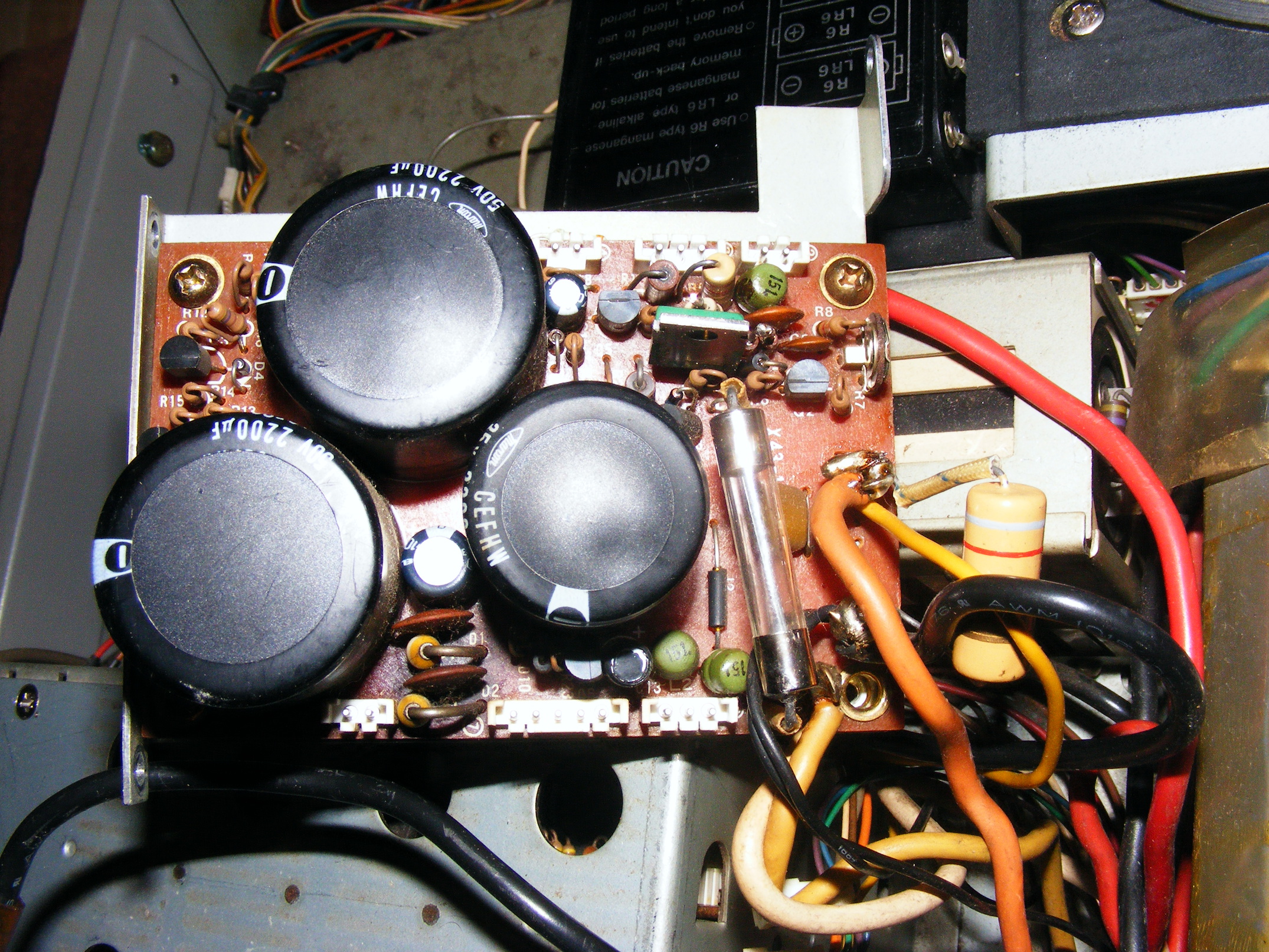
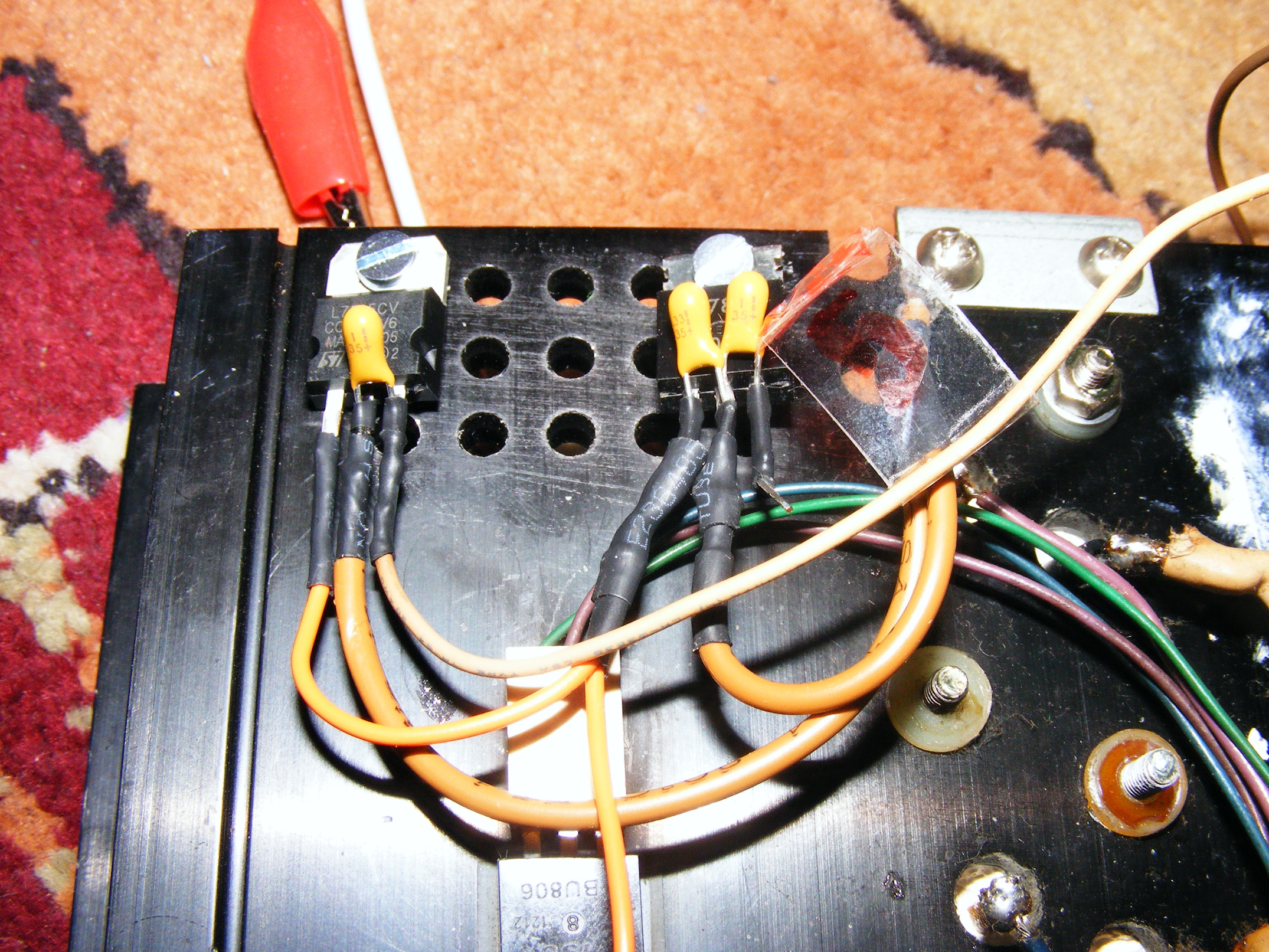
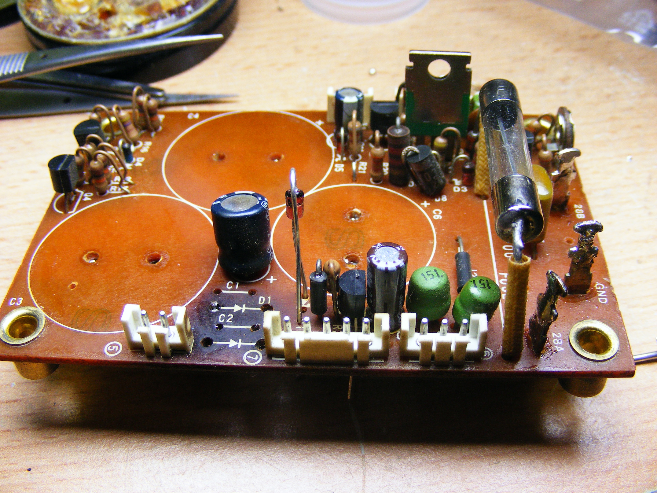
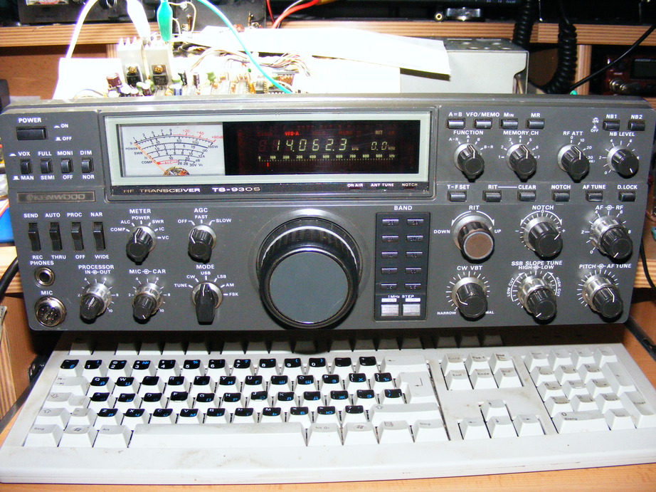
Project TS-930S ...over the years I repaired a couple of TS-930, and I'm very happy to see that people still love this radio... this is how I got in touch with the inside of the great TS-930...  When I got my license more than 10 years ago I struggled to get a radio - not that easy with 25Eur pocket money a month :-). Now, time passed by and I had the possibility to play with lots of different gear, mondern and post modern. As a CW-guy I really fell in love with the TS-930 I got when I was 15 years old. Ever since, this transceiver gave me pleasure on the bands. Now, after years of operation, it died the electronic death. There is no display, I can not switch to transmit. If I change bands I can not hear a relay as I was used to. There is NO reaction of anything. But the reflection meter on the front is always at the end, on the far right side. Download the Service manual in high resolution (93MB) which I found many years ago on WE0H's Website here First of all, I checked the voltages at the Power Supply. 28V were present, but no 21V. So I opened everything and realized that the pre-owner already did some modification. Obviously he knew about the W6NL-modifications because there was already a 7808 and a 7815 attached to the heat sink. What I wondered was that one of the Tantal-Cs was soldered the wrong way... it didn't blow up because it was never used (why???) Anyway, I got the Power Supply Unit out and renewed everything what seemed to be burned.
What I replaced: (you can see the power supply schematic here)
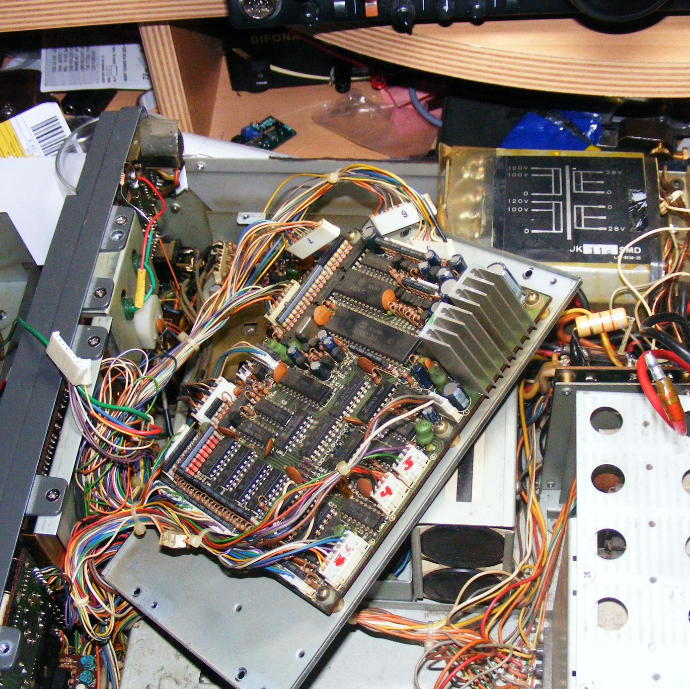
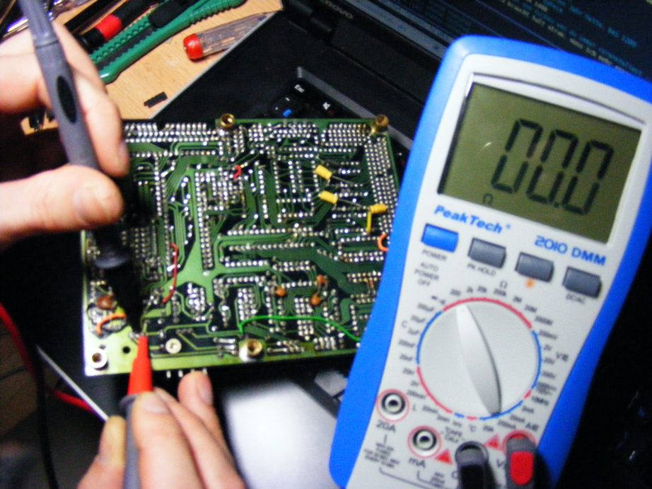
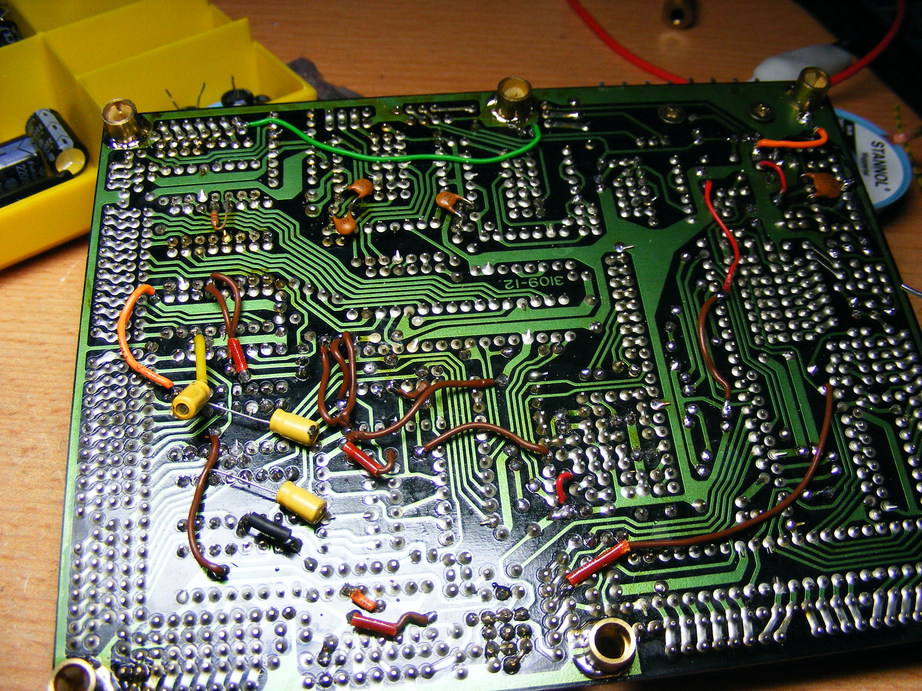
Okay, I connected everything back. I switched on the Transceiver after connecting everything and - nothing happened!. So I got the digital unit out and resoldered every through hole connection. I inserted silverplated copper-wire.
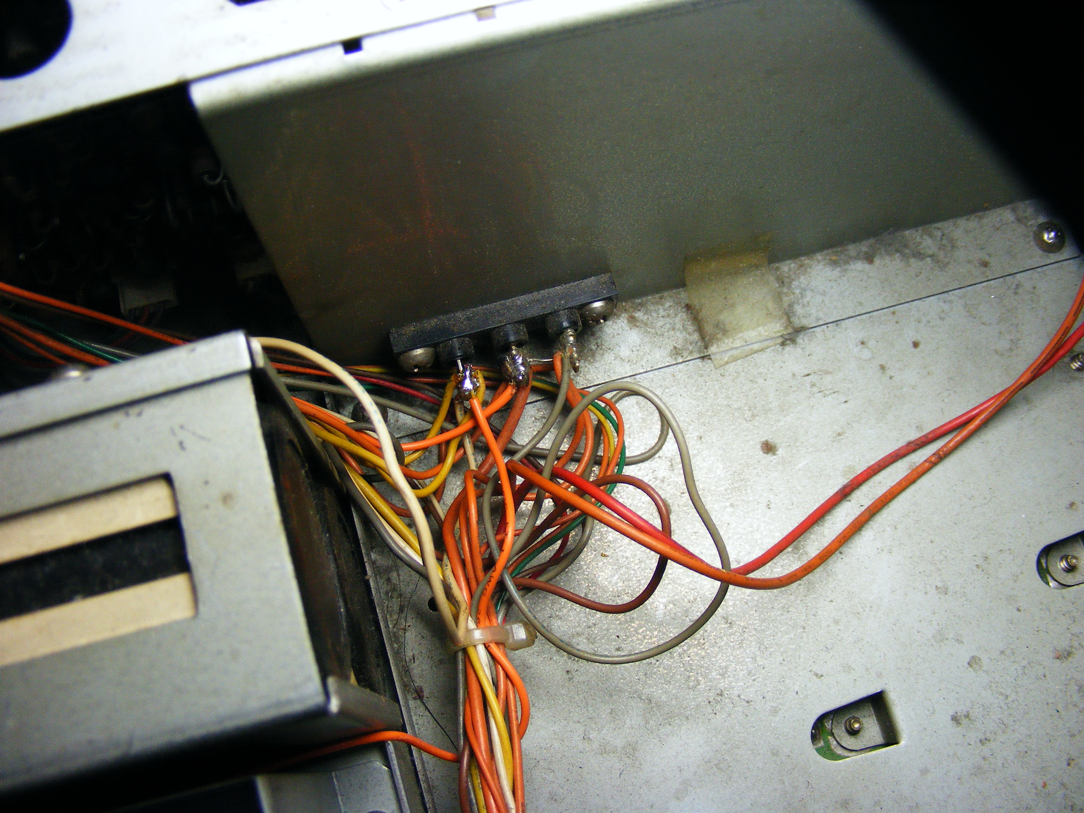
After putting the digital board back in place and connecting everything I switched it on - nothing. No Display, the Meter is still at 120% and I can hear a continious beep out of the speaker. What the hell is going on in there? I disconnected J9 and now the meter shows a 0, when I switch to transmit I can see the 'transmit-lamp'. Okay, but no display, no sound out of the speaker. Means that there is a PLL-problem as well... I started measuring the voltages to compare them with the service manual. Here my results I don't know why I get hose values. I also don't know why they are all about the same. I'm also not sure if the connection on Picture 4 between pin 2 and 3 (from the right) has to be... If it really has to be - why is it such a thin wire then?
I started to adjust the PLLs according the the service manual. Although I had no display the TX was working and I could figure out on what frequency I'm sending with an simple frequency counter.
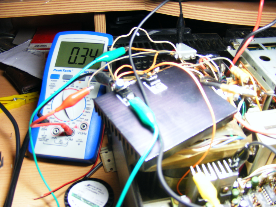
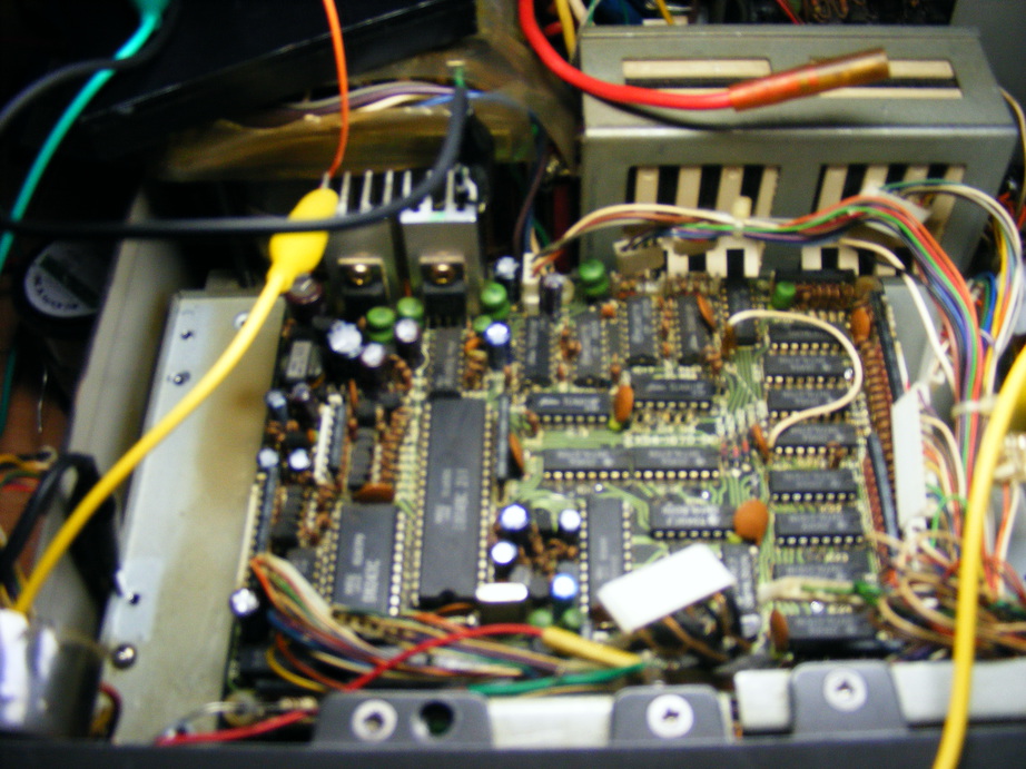
digital board, connector 1 pin 3 showed 0V. Why? There should be some 24V, generated by an potential divider on the heat sink. I checked this divider (a resistor) and saw the all the wires were unsoldered from the heat. And it also lost its color. So I replaced it (33Ohm, 2W) by 33Ohm 10W and measured the current. 1.3A - wow! I checked everything around T1 on the digital board and detected a problematic part: Q15. I replaced this 2SC2274 by an BC639 and I had display!. I also replaced Q15 to be on the safe side. I checked the PLL-voltage again, re-adjusted a bit and switched out everything. It was 2 in the morning. Luckily I'm a student, so I can spend an hour or two more in the bed the next morning.
I want to refer to Thread in QRZ-Forum and to say tnx to KE3WD, G4COE and W9GB. |

